How Can custom hydraulic hoses Improve Equipment Safety and Reliability?
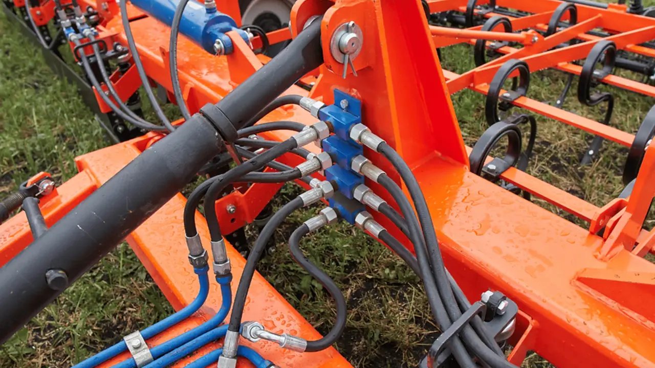
A custom hydraulic hose improves equipment safety by matching pressure rating, inside diameter, temperature range, fluid compatibility, fitting type, bend radius, and routing to the machine rather than forcing a stock assembly into the installation. Hydraulic systems commonly work at 2,000–5,000 psi, while some hose constructions are tested at burst pressures near four times rated working pressure. SAE J517, SAE J1273, and ISO hydraulic-hose requirements also address pressure, impulse performance, installation, and compatibility. Correctly specified assemblies reduce abrasion, twisting, fitting stress, fluid leakage, and heat buildup. Reliability comes from treating the hose, fittings, fluid, routing, and operating environment as one assembly rather than separate parts.
A hose can have the correct thread and still be unsuitable for the machine. Working pressure, pressure spikes, flow rate, oil temperature, outside temperature, movement, chemical exposure, and installation space all affect service life. A 1/2-inch hose rated for one pressure range cannot automatically replace another 1/2-inch hose with different reinforcement or temperature limits.
Pressure deserves attention first because hydraulic systems do not operate at one perfectly stable number. Pumps, directional valves, cylinders, accumulators, and sudden load changes can create short pressure peaks above normal operating pressure. SAE J1273 guidance states that system pressure, including surges, must remain within the rated working pressure of the hose assembly.
A machine running normally at 3,000 psi may still need a hose selected for higher operating demands if repeated pressure peaks occur during cylinder reversal, lifting, braking, or attachment movement.
Burst pressure should not be treated as normal operating capacity. A hose listed with a 12,000 psi minimum burst pressure may have a rated working pressure near 3,000 psi, giving roughly a 4:1 relationship in many hydraulic hose designs. Burst data comes from destructive testing and is not permission to operate the hose close to that number.
Pressure cycling matters almost as much as maximum pressure. A stationary hydraulic line that experiences 500 cycles per week has a different operating pattern from a loader hose flexing and pressurizing several thousand times during the same period. Some high-temperature SAE 100R1 hose products are validated to 450,000 impulse cycles, around three times a stated 150,000-cycle benchmark for their class.
That repeated cycling places the reinforcement under alternating stress. Steel-wire braid or spiral reinforcement carries most of the pressure force, while the inner tube contains the fluid and the outer cover protects the reinforcement. Once abrasion exposes steel wire, moisture and mechanical contact can damage a structure that may still look usable from several feet away.
Size selection adds another engineering issue: pressure rating alone does not control flow. A hose with an inside diameter that is too small increases fluid velocity and pressure loss. More hydraulic energy is then converted to heat, raising oil and hose temperature and making the pump work under less favorable conditions.
For comparison, increasing internal diameter changes flow area quickly because area depends on the square of radius. Moving from a 1/2-inch bore to a 3/4-inch bore increases cross-sectional area from about 0.196 to 0.442 square inch, more than a 125% increase. That difference can substantially change velocity at the same gallons-per-minute flow rate.
| Specification | What should be checked | Example range or effect |
|---|---|---|
| Working pressure | Normal pressure plus surges | Often 2,000–5,000 psi on mobile equipment |
| Inside diameter | Required flow and acceptable velocity | 1/2 in. and 3/4 in. have very different flow areas |
| Oil temperature | Tube compound limit | Many general hydraulic hoses operate near -40°C to +100°C |
| Bend radius | Hose construction and size | Large hoses may require 200 mm or more |
| Fitting angle | Port position and routing | Straight, 45°, and 90° ends |
| Cover protection | Abrasion, weather, heat | Sleeve or high-abrasion cover where required |
Temperature then has to be checked against both the fluid and the surroundings. Many common hydraulic hose constructions are rated around -40°C to +100°C, while specialized high-temperature products can reach continuous ratings near +135°C and intermittent exposure around +149°C. Those limits vary by tube compound and manufacturer.
A hose carrying 80°C oil beside an exhaust component is exposed to two heat sources rather than one. Radiant heat can age the outer cover even when fluid temperature remains within specification. Routing farther from the heat source is preferable; where space prevents that, a suitable heat sleeve can reduce direct thermal exposure.
Fluid chemistry creates a separate compatibility requirement. Petroleum-based hydraulic oil, water-glycol fluid, phosphate ester fluid, biodegradable ester fluid, and synthetic media do not interact with elastomers in the same way. A tube compound suitable for one fluid can swell, soften, harden, or lose strength in another.
That is why a properly prepared specification should identify the exact fluid rather than state “hydraulic oil.” A machine converted in 2024 from a conventional mineral oil to a biodegradable fluid may need compatibility checks for the tube, cover, seals, O-rings, and couplings, not merely a fluid change in the reservoir.
Mechanical routing comes next because many field problems start outside the hose. A hose installed 30 mm from a moving steel edge may contact that surface every time a boom, mast, or steering joint moves. Thousands of small rubbing movements can remove the cover even though working pressure remains well below the hose rating.
Abrasion-resistant covers can extend service in contact-prone environments. Manufacturer testing under ISO 6945 has shown specialized cover constructions lasting up to 25 times or, for some premium designs, up to 300 times longer than a manufacturer's standard cover in controlled hose-to-hose or hose-to-metal abrasion tests. Those laboratory figures should not be converted directly into years of field life because dirt, motion, pressure, and contact geometry vary by machine.
Good routing still comes before protective sleeves. Clamps can keep long hose runs away from moving parts, but clamp diameter must match the hose. An oversized clamp allows movement and rubbing; an excessively tight clamp can restrict the hose or concentrate stress in one location.
Bend radius requires the same attention. Each hose size and construction has a stated minimum bend radius. One SAE 100R16-type 1.25-inch hose, for example, is specified with a minimum bend radius around 210 mm and a working pressure near 2,300 psi. A smaller high-temperature 1/4-inch SAE 100R1 hose may have a bend radius near 102 mm.
Forcing either hose below its specified radius changes the geometry of the reinforcement. The inside of the bend compresses while the outside stretches, concentrating repeated stress in a small area. Bending immediately behind the fitting adds stress where the hose and coupling already transfer pressure and mechanical forces.
When the available space cannot support the required radius, changing fitting geometry is usually better than forcing the hose around the corner. A 45° or 90° fitting can move the bend away from the coupling and reduce the amount of hose needed.
Length also needs allowance for machine movement and pressure-related dimensional change. A hose cut exactly from port to port while the equipment is stationary may become tight when a cylinder reaches full extension. A hose that is 10–15% longer without considering routing can create the opposite problem by forming loops that rub against guards or adjacent lines.
Custom assembly work solves both issues by measuring the hose path through the machine's full range of motion. customized hydraulic hose solutions can specify length, hose type, end fittings, fitting orientation, and protective components around the installation rather than selecting an assembly only by nominal diameter.
Fitting orientation matters especially when both ends use elbows. If two 90° ends must sit at different angles, incorrect clocking forces the hose to twist during installation. Hydraulic hose is designed to flex, but continuous axial twisting changes the way reinforcement wires carry pressure and can accelerate damage near the coupling.
Crimping adds another controlled dimension. The hose and fitting must be approved as a compatible assembly, and the crimp diameter has to stay within the manufacturer's specified tolerance. Mixing a hose from one system with an unverified coupling because the parts appear to fit can produce an assembly whose pressure and impulse performance has never been validated.
Assembly cleanliness deserves equal attention during replacement. Cutting hose can leave rubber particles and metal contamination inside the bore. If debris enters a servo valve or proportional valve with small internal clearances, a replacement intended to restore reliability can introduce another maintenance problem.
A 2024 hydraulic maintenance program should therefore record hose part number, machine position, length, end type, fitting angle, installation date, and inspection condition. A fleet with 100 machines can then reorder an identified assembly instead of measuring a damaged hose after each shutdown.
Inspection intervals should follow machine duty rather than one universal calendar rule. Equipment operating 2,000 hours per year in a clean indoor plant does not expose hoses to the same conditions as a quarry loader operating around rock, dust, vibration, water, and frequent articulation. Visual inspection should look for abrasion, exposed reinforcement, cracked covers, leaks, damaged fittings, kinks, flattened sections, and movement at the coupling.
Oil on the outside of a hose should never be checked with a bare hand while the system is pressurized. A pinhole leak can release a narrow high-pressure stream capable of penetrating skin. The machine should be depressurized according to the equipment manufacturer's service procedure before technicians handle a suspected leaking assembly.
Replacement planning also benefits from keeping repeated hose positions standardized. If 12 excavators use the same boom-hose assembly, maintaining an approved specification and a small replacement stock can shorten repair time compared with rebuilding every hose from measurements after a breakdown. Standardized records also reduce fitting, length, and pressure-rating identification errors.
Cost comparisons should therefore include more than hose purchase price. A lower-priced assembly that lasts 1,000 operating hours instead of 2,000 doubles the replacement frequency before labor, fluid cleanup, transportation, and lost machine time are counted. A more suitable assembly does not need to be the most expensive; it needs verified specifications for the actual pressure, temperature, fluid, routing, and movement.
A safe hydraulic hose is an engineered pressure-containing assembly, not a piece of rubber cut to length. Pressure class, impulse resistance, internal diameter, temperature range, bend radius, tube chemistry, reinforcement, cover material, fitting compatibility, crimp dimensions, orientation, routing, cleanliness, and inspection history all contribute to how consistently the equipment operates.